node-red-contrib-mcp4725 1.0.0
Node-RED nodes for MCP4725 DAC over I2C
node-red-contrib-mcp4725
Node-RED nodes for controlling the MCP4725 digital-to-analog converter over the I2C bus.
This package provides a simple output node for setting the analog output voltage of an MCP4725 DAC module directly from Node-RED. It is intended for experimental automation, prototyping, education, and embedded control applications.
Features
- control of MCP4725 DAC over I2C
- support for raw DAC values from 0 to 4095
- support for percentage input from 0 to 100 %
- support for voltage input from 0 to configured VDD
- optional input clamping
- optional EEPROM write
- reusable configuration node for I2C bus, address, and supply voltage
- output message with information about I2C address, selected mode, written bytes, and DAC value
Installation
Install the package directly from the Node-RED Palette Manager:
Menu → Manage palette → Install
Search for:
node-red-contrib-mcp4725
and click Install.
Alternatively, install it from the Node-RED user directory:
cd ~/.node-red
npm install node-red-contrib-mcp4725
After installation, restart Node-RED if required.
Nodes
This package contains two Node-RED nodes:
| Node | Type | Description |
|---|---|---|
mcp4725-config |
configuration node | Stores I2C bus number, MCP4725 address, and VDD |
mcp4725-out |
output node | Writes an analog output value to the MCP4725 DAC |
Example flow
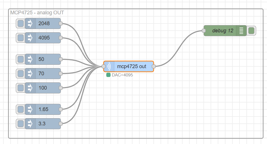
The following example shows the mcp4725-out node controlled by several inject nodes with different input values.
Configuration node
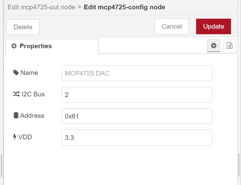
The mcp4725-config node defines the hardware parameters of the MCP4725 module.
Parameters
| Parameter | Description | Example |
|---|---|---|
| Name | Optional name of the configured device | MCP4725 DAC |
| I2C Bus | I2C bus number used by the target system | 2 |
| Address | I2C address of the MCP4725 module | 0x61 |
| VDD | Supply voltage of the MCP4725 module | 3.3 |
Example configuration:
I2C Bus: 2
Address: 0x61
VDD: 3.3
Output node
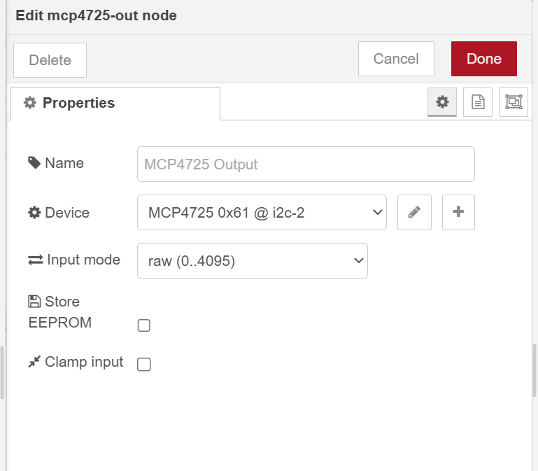
The mcp4725-out node writes the required value to the MCP4725 DAC.
Parameters
| Parameter | Description |
|---|---|
| Name | Optional name displayed on the node |
| Device | Selected mcp4725-config configuration node |
| Input mode | Defines how msg.payload is interpreted |
| Store EEPROM | Stores the value into MCP4725 EEPROM |
| Clamp input | Limits values outside the valid range instead of throwing an error |
Input modes
The node supports three input modes.
Raw mode
In raw mode, msg.payload must be a number from 0 to 4095.
{
  "payload": 2048
}
This writes approximately half of the full-scale output voltage.
Percent mode
In percent mode, msg.payload must be a number from 0 to 100.
{
  "payload": 50
}
The value is internally converted to a 12-bit DAC value.
Voltage mode
In voltage mode, msg.payload represents the required output voltage.
{
  "payload": 1.65
}
The value is converted according to the configured VDD.
For example, if VDD is set to 3.3 V, then 1.65 V corresponds approximately to the raw DAC value 2048.
Clamp input
If Clamp input is enabled, values outside the valid range are automatically limited to the nearest allowed value.
Examples:
| Input mode | Input value | Result |
|---|---|---|
| raw | 5000 |
4095 |
| raw | -100 |
0 |
| percent | 150 |
4095 |
| percent | -20 |
0 |
| voltage | value above VDD | 4095 |
If Clamp input is disabled, invalid values cause an error.
Store EEPROM
If Store EEPROM is enabled, the output value is written into the MCP4725 EEPROM.
This means the DAC can restore the stored value after power-up.
Use this option only when needed, because EEPROM has a limited number of write cycles.
If Store EEPROM is disabled, the node uses a faster write operation and the value is not stored permanently.
Output message
After a successful write operation, the node sends the message to its output.
The output msg.payload contains the raw DAC value from 0 to 4095.
Example output:
{
  "payload": 2048,
  "i2c": {
    "busNumber": 2,
    "addressHex": "0x61",
    "addressDec": 97,
    "bytes": [8, 0],
    "mode": "raw",
    "vdd": 3.3,
    "storeEEPROM": false
  }
}
The msg.i2c object contains additional diagnostic information about the I2C write operation.
Hardware requirements
This node requires:
- Node-RED
- MCP4725 DAC module
- system with I2C support
- enabled I2C interface
- correct I2C wiring
- compatible Linux-based target device, such as Raspberry Pi, Luckfox, or another embedded board with I2C support
Wiring
Typical MCP4725 module connection:
| MCP4725 pin | Target device |
|---|---|
| VCC / VDD | 3.3 V or 5 V, depending on the module |
| GND | GND |
| SDA | I2C SDA |
| SCL | I2C SCL |
| OUT | Analog output |
Make sure that the configured VDD value matches the real supply voltage of the MCP4725 module.
Platform note
This node uses the i2c-bus package and is intended to run on Linux-based devices with I2C support.
On Windows, the node may install successfully, but real I2C communication is not supported unless a compatible I2C interface and driver are available.
Notes
For reliable operation, make sure that:
- the I2C interface is enabled,
- the correct I2C bus number is selected,
- the correct MCP4725 address is configured,
- the MCP4725 module is connected correctly,
- the configured VDD matches the real supply voltage,
- the input value matches the selected input mode.
License
This project is licensed under the MIT License.