node-red-contrib-avrdb28-expander 0.0.4
Node-RED node for AVR128DB28 universal I2C IO expander firmware
node-red-contrib-avrdb28-expander
Node-RED node for controlling an AVR128DB28 microcontroller used as a universal I2C I/O expander.
This package provides the avrdb28-pin node, which allows selected pins of the AVR128DB28 microcontroller to be configured and controlled directly from Node-RED through the I2C bus.
The node is intended for experimental automation, prototyping, education, and testing of software-based control systems.
Features
- communication with AVR128DB28 through I2C
- configuration of individual microcontroller pins
- support for digital inputs and outputs
- support for input pull-up mode
- support for analog input measurements
- support for PWM output
- support for DAC output
- simple integration into Node-RED flows
- suitable for replacing several separate I/O modules with one programmable device
Installation
The package can be installed directly from the Node-RED Palette Manager.
Open Node-RED and go to:
Menu → Manage palette → Install
Search for:
node-red-contrib-avrdb28-expander
and click Install.
Alternatively, the package can be installed from the Node-RED user directory:
cd ~/.node-red
npm install node-red-contrib-avrdb28-expander
After installation, restart Node-RED if required.
Node
avrdb28-pin
The avrdb28-pin node is used to configure and control one selected pin of the AVR128DB28 microcontroller.
Each node instance represents one physical pin. Multiple nodes can be used in one flow to control or read multiple pins.
Example flow
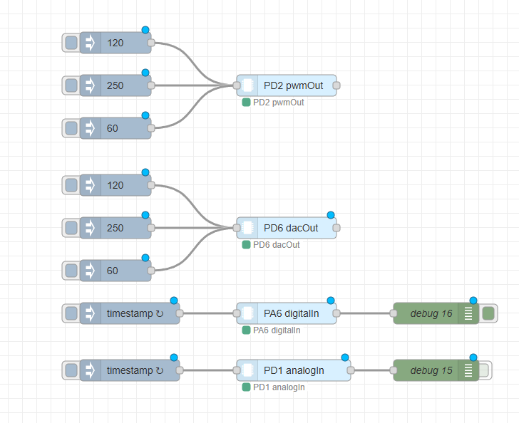
The following example shows the integration of the avrdb28-pin node in a Node-RED flow.
Node configuration
The node configuration dialog allows the user to define the I2C communication parameters, selected pin, reference voltage, and operating mode.
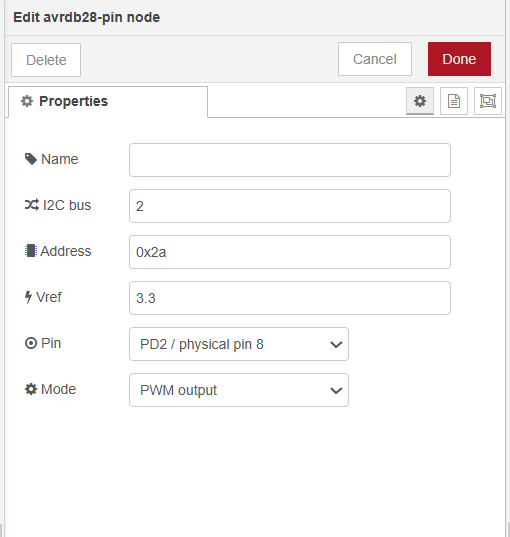
The following parameters can be configured:
| Parameter | Description |
|---|---|
| Name | Optional name displayed on the node |
| I2C bus | I2C bus number used by the target device |
| Address | I2C address of the AVR128DB28 firmware |
| Vref | Reference voltage used for analog value conversion |
| Pin | Selected AVR128DB28 pin |
| Mode | Operating mode of the selected pin |
Default I2C address:
0x2a
Default reference voltage:
3.3 V
Supported pins
The following AVR128DB28 pins are available in the node:
PA7, PC0, PC1, PC2, PC3,
PD1, PD2, PD3, PD4, PD5, PD6, PD7,
PF0, PF1,
PA0, PA1, PA4, PA5, PA6
Pins PA2 and PA3 are reserved for I2C communication and are intentionally not available in the node configuration.
Supported modes
The available modes depend on the selected pin.
| Mode | Description |
|---|---|
| disabled | Pin is disabled |
| digitalIn | Digital input |
| inputPullup | Digital input with internal pull-up |
| digitalOut | Digital output |
| analogIn | Analog input / ADC measurement |
| pwmOut | PWM output |
| dacOut | DAC analog output |
Not all pins support all modes. The configuration dialog automatically displays only the modes supported by the selected pin.
Input messages
The node is triggered by an incoming message.
Digital output
For digital output mode, msg.payload can be:
true / false
1 / 0
"on" / "off"
"high" / "low"
Example:
{
  "payload": true
}
PWM output
For PWM output mode, msg.payload must be a value from 0 to 255.
Example:
{
  "payload": 128
}
The output message also contains the calculated percentage value in msg.percent.
DAC output
For DAC output mode, msg.payload must be a value from 0 to 255.
Example:
{
  "payload": 200
}
The output message also contains the calculated voltage in msg.voltage.
Digital input
For digital input mode, any incoming message triggers a read operation.
Example input:
{
  "payload": true
}
Example output:
{
  "payload": 1,
  "pin": "PA7",
  "mode": "digitalIn",
  "raw": 1
}
Input pull-up
For input pull-up mode, any incoming message triggers a read operation.
In this mode, the pin is pulled high internally. If a button is connected to ground, the output property msg.pressed is set to true when the button is pressed.
Example output:
{
  "payload": 0,
  "pin": "PA7",
  "mode": "inputPullup",
  "raw": 0,
  "pressed": true
}
Analog input
For analog input mode, any incoming message triggers an ADC read operation.
Example output:
{
  "payload": 2048,
  "pin": "PD1",
  "mode": "analogIn",
  "raw": 2048,
  "voltage": 1.65
}
The voltage is calculated from the configured reference voltage.
Firmware
This Node-RED node requires compatible firmware running on the AVR128DB28 microcontroller.
The firmware implements an I2C register map that allows Node-RED to configure pin modes, write output values, and read input values from the microcontroller.
The firmware source code is included in the firmware directory of this package.
Recommended structure:
firmware/
└── avrdb28_expander_firmware.c
or:
firmware/
└── avrdb28_expander_firmware.ino
depending on the development environment used.
Firmware requirements
The firmware must support the register map used by this Node-RED node.
System registers
| Register | Address | Description |
|---|---|---|
| DEVICE_ID | 0x00 | Device identification |
| FW_VERSION | 0x01 | Firmware version |
| PIN_COUNT | 0x02 | Number of supported pins |
| LAST_ERROR | 0x03 | Last firmware error |
Pin register bases
| Register base | Address | Description |
|---|---|---|
| MODE_BASE | 0x20 | Pin mode registers |
| CAP_BASE | 0x40 | Pin capability registers |
| OUT_LO_BASE | 0x60 | Output low byte registers |
| OUT_HI_BASE | 0x80 | Output high byte registers |
| IN_LO_BASE | 0xA0 | Input low byte registers |
| IN_HI_BASE | 0xC0 | Input high byte registers |
Supported firmware modes
| Mode | Value |
|---|---|
| disabled | 0 |
| digitalIn | 1 |
| inputPullup | 2 |
| digitalOut | 3 |
| analogIn | 4 |
| pwmOut | 5 |
| dacOut | 6 |
Uploading the firmware
Before using the Node-RED node, the firmware must be uploaded to the AVR128DB28 microcontroller.
General steps:
- Connect the AVR128DB28 microcontroller to the programming interface.
- Open the firmware project from the
firmwaredirectory. - Compile the firmware.
- Upload the firmware to the microcontroller.
- Connect the microcontroller to the target device through the I2C bus.
- Enable I2C on the target system.
- Configure the correct I2C bus number and address in the Node-RED node.
The default I2C address expected by the node is:
0x2a
Hardware requirements
This node requires:
- Node-RED
- system with I2C support
- enabled I2C interface
- AVR128DB28 microcontroller
- compatible firmware uploaded to the microcontroller
- correct electrical connection between the target system and the AVR128DB28
Notes
The node is intended mainly for experimental, educational, and prototyping purposes.
It is not intended to replace certified industrial PLC or safety PLC systems in safety-critical applications.
For reliable operation, make sure that:
- the I2C bus is enabled,
- the correct I2C bus number is selected,
- the correct I2C address is configured,
- the AVR128DB28 firmware is uploaded,
- the selected pin supports the selected operating mode.
License
This project is licensed under the MIT License.